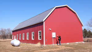
Matt's Weekly Shop Update
Kitchen Island, Barn Power – March 2024 Update
Welcome to my shop! This is a quick update to let you know what I’ve been up to. This big chunky thing is the leg
A bandsaw mill is pretty dangerous. Not only do you want to protect from body parts coming in contact with the wheels and blade but you also need to contain the the blade if it breaks.
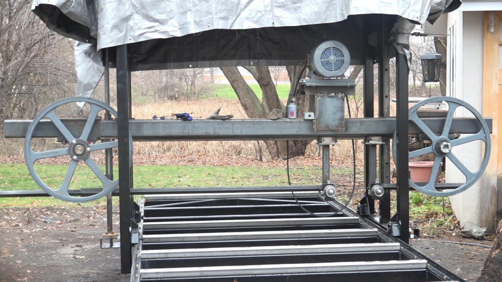
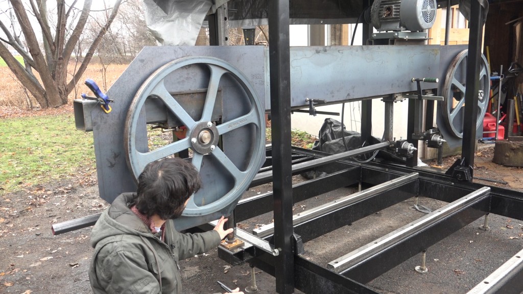
Here’s a look at the mill with no blade guards. The wheels need to be guarded, the blade return between the wheels needs to be guarded and the area where the blade leaves the idle wheel and goes over to the blade guide needs to be guarded.
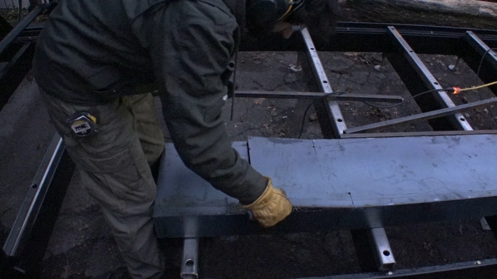
I want to have the guards mount directly to the beam so on both sides some allocation needs to be made for the parts of the bearings and wheel mounts that are on the front side of the beam. Here you can see the idle mount needs to be behind the guard and there needs to be room for the mount to still slide along the beam while the guard stay stationary.
The saw head is 12′ long so I’m going to make the guards in three parts. One for each wheel and one box for the top side of the blade.
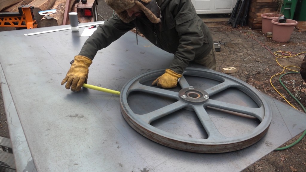
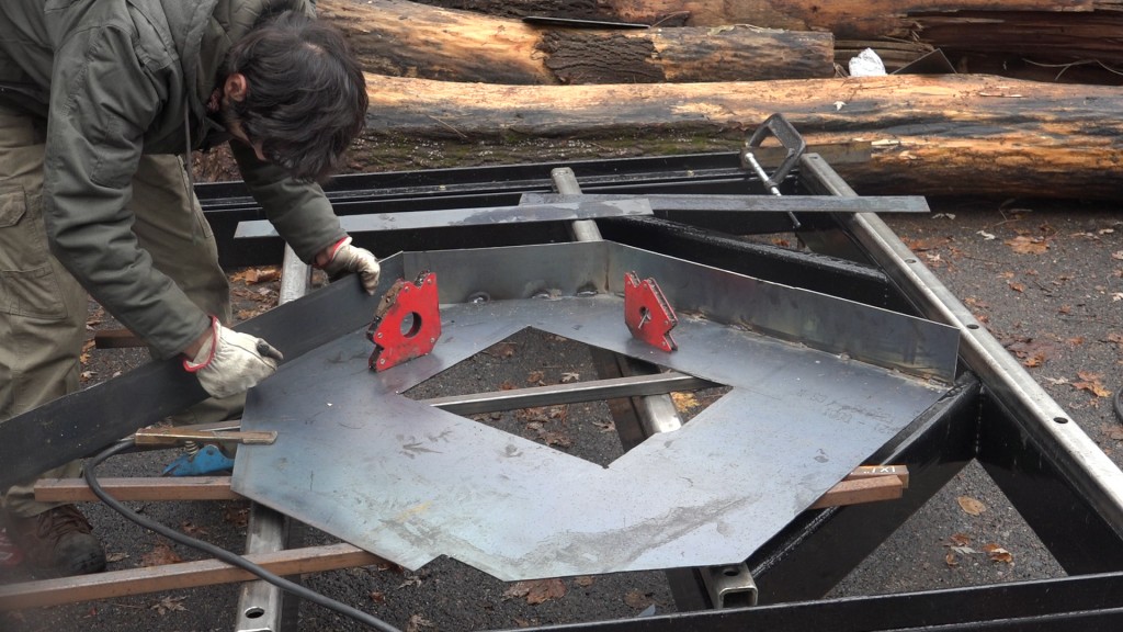
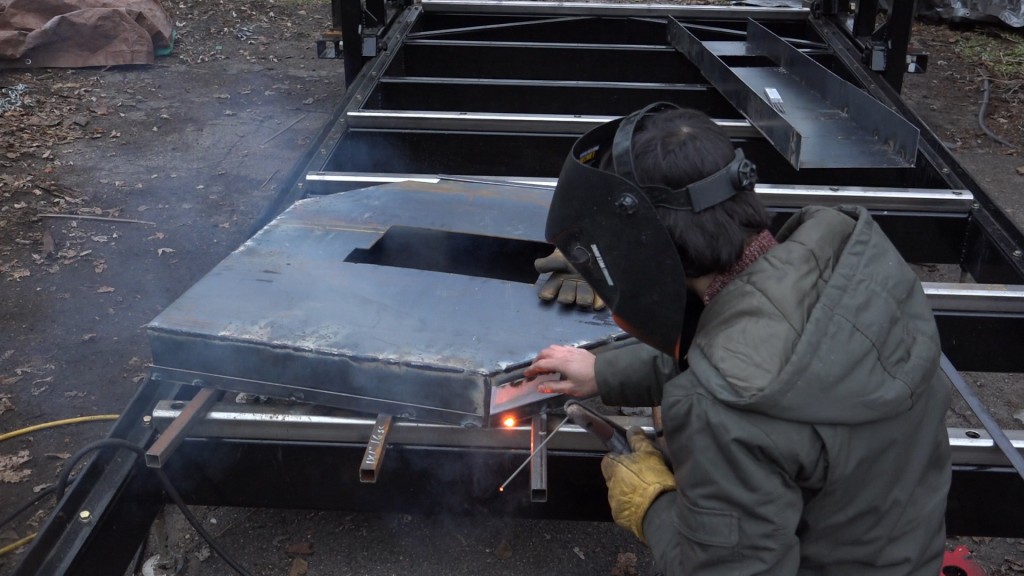
To make the blade guards, I’m using two 4’x8′ 12 gauge (~.1″ thick) steel sheets. This of course is thicker than is really necessary but since I’m going to be welding this all together and not bending it, the thicker material will be easier to weld with my stick welder. I also know my self and these guards are going to have to take a beating and will need to support me standing on them to access to the top of the mill. I drew both backs of the wheel guards out onto the steel first to make sure the measurements would work. I placed a wheel onto the drawing to check the clearance on all sides so the wheel wouldn’t contact the walls of the guard.
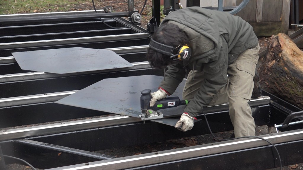
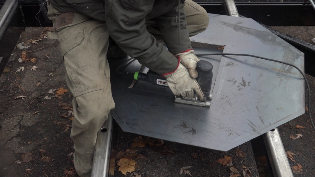
The blade on my circular saw was toast at this point so while I was waiting for a replacement to come in, I switched to using my jigsaw with a metal cutting blade to cut out the panels.
Each guard has some material removed from the inside to provide clearance to the stuff on the beam. These cut outs will be used later.
I clamped the back plates to the mill to check to make sure everything was going to work. I noticed one issue which I hadn’t before: the back of the guard will contact the platform which supports the sawhead. Luckily that can be easily resolved by notching the back of the guard. The door will clear the platform so it can be left as is. Another issue was the motor mount. When I built that, I added a piece of sheet steel to the front of it to close it in and provide some racking resistance. This panel now sits on the beam and the guards will need to be notched around it. When I built the motor mount I was planning on having the guards mount 1/2″ or so off of the beam so it’s placement wouldn’t have been an issue.
Now I can start adding the walls to the guards. I cut 4″ wide strips from the offcuts and welded those around the perimeter. I started by trying 1/8″ 7018 rods since they should be gentler than the 6011 rods I had been using however I had a really hard time getting the arc to start at a low enough amperage to not blow through the material. I switched to using 6011 and kept lowering the amps until I could comfortably run a bead without blowing through the material. 90 amps was a good setting but it was quite difficult to strike and maintain an arc so I ended up using the 6011 rods at 100 amps to tack all the parts in place and did the actual welding with 1/16″ 6013 rods at 60 amps. These rods ended up working really well but they don’t last very long since they’re so thin.
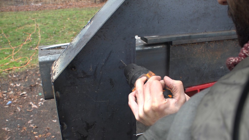
Everything looked good so I could drill and tap for the mounting bolts.
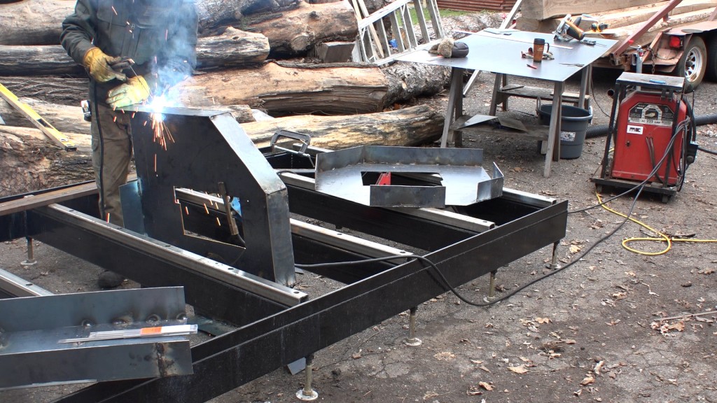
I repeated the same process for the drive side. Here you can see the dust chute going on.
Next I can focus on this transverse area. I outlined the motor mount while I had the piece of steel clamped in place so I knew the exact location for the cut out.
I started the cut out before welding the walls on since it would be easier that way. I didn’t want to remove the material however since the cut out went all the way to the edge so I left some tabs in place that I could easily slice through once the walls were in place. Oh and of course, I welded the walls on the wrong side, so the whole thing was backwards and I had to make the cut out again. Joy.
With the guarding down, I welded the entirety of the seams. This will make the guards weather sealed but I did leave some gaps along the bottom for water to escape if any finds its way inside.
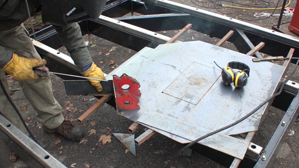
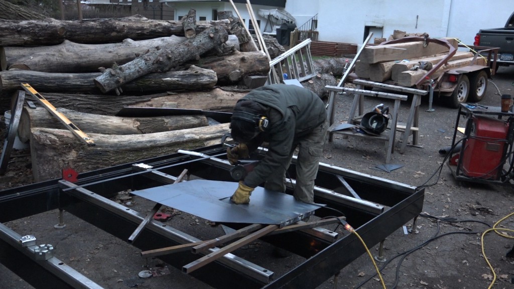
Next I can start working on the doors. To get the side and shape correct, I laid the housings down onto the sheet and traced around them. I extended this outline by 3/16″ which will allow space for the 1/8″ banding that I will be using and some space so the door can easily slip over this box thing.
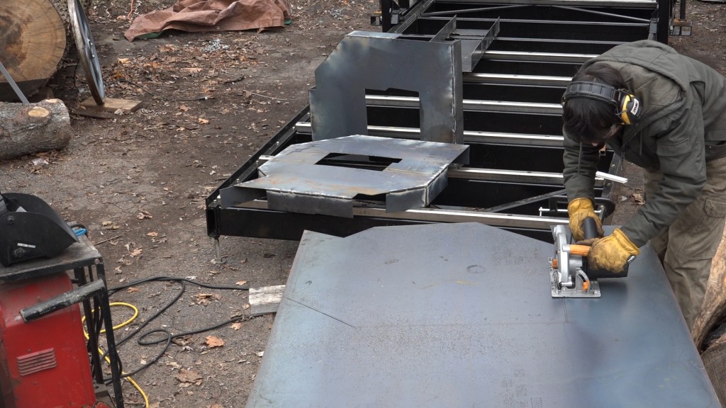
The replacement blade came for my circular saw so these were much quicker to cut out.
To space the banding off of the guard body I used 6 index cards.
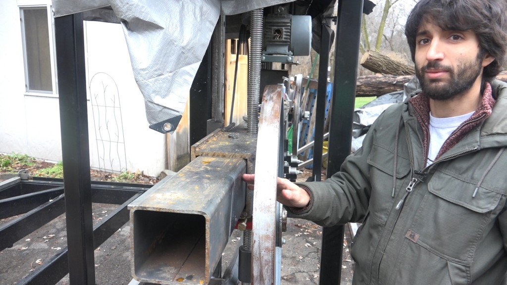
The drive shaft is pretty long and extends past where the door is. I decided to make the guards less deep and create a bump out on the dive door for the shaft.
Next I can add the door to the transverse box with a piano hinge that I welded in place.
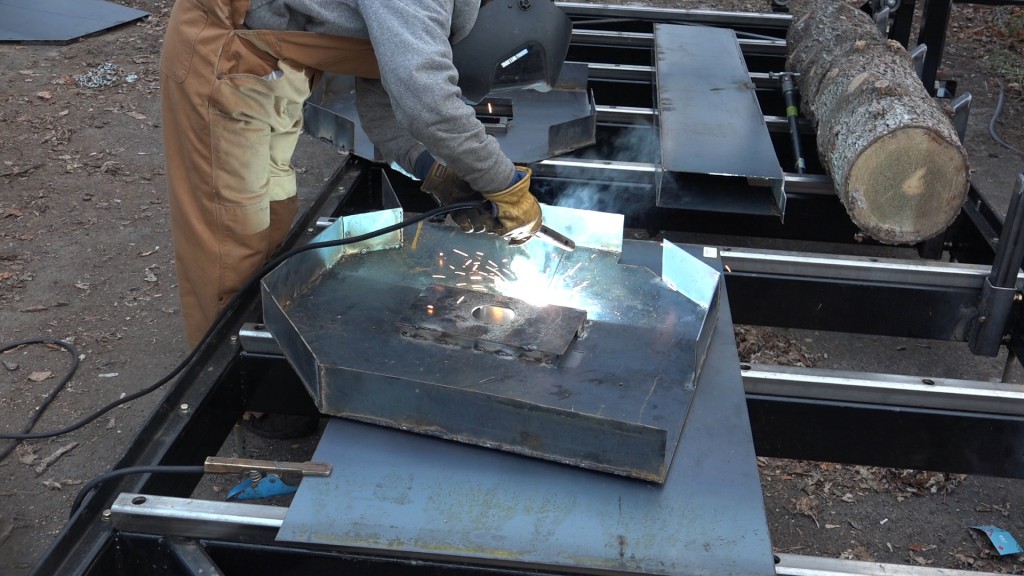
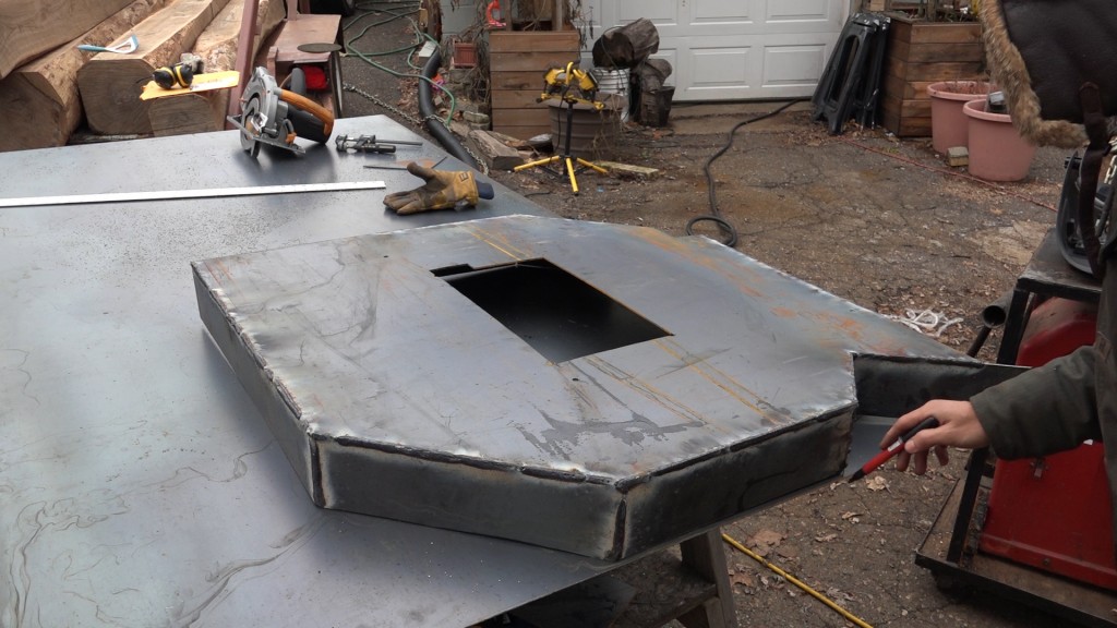
Lastly I can fill in the back area. I added some 1×1 tube, drilled a hole in the cutout from before for the shaft to pass through, and welded the cut out back in place on top of the square tube.
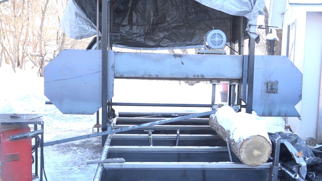
Here are the guards with the wheel doors removed. You can see the opening for the idle side is slotted so the shaft can slide in and out to be tensioned. This slot is oversized so in the future I can use longer blades. Once I know the final travel for the blades I have now, I’ll add a removable cover to the opening that won’t be used and that will keep fingers and hands from going into the wheel.
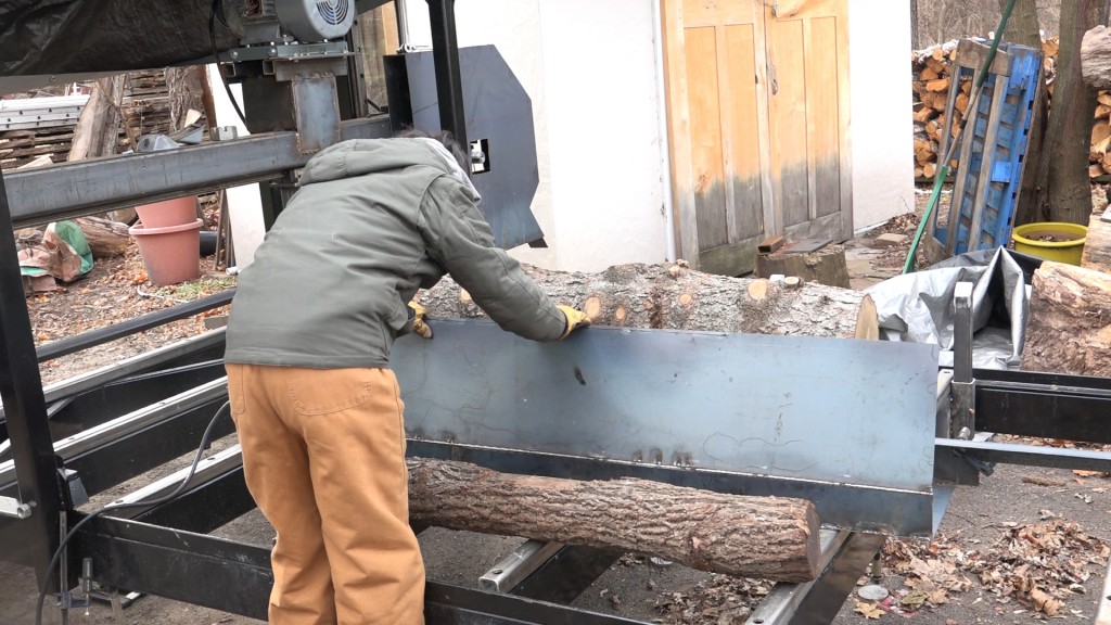
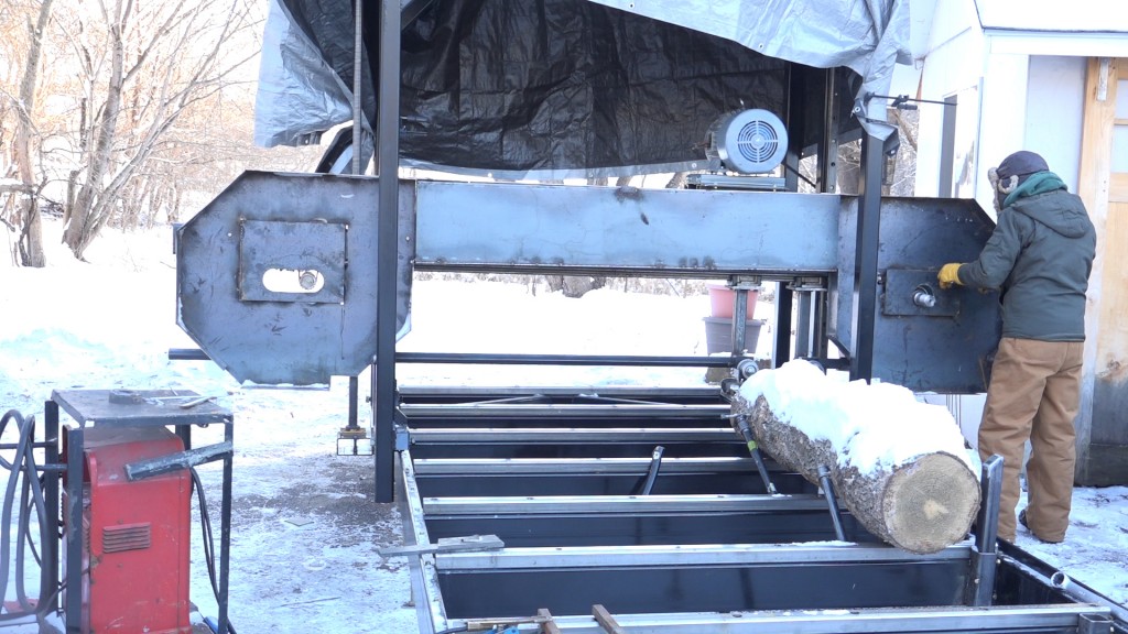
Here’s a look with the doors installed. I still need to add the guard that will go across the bed but since I need to start calibrating this mill, less guarding will make that process easier.
Metal Circ saw: http://amzn.to/2c3DaSS
Replacement Blade: http://amzn.to/2inblM0
Jig Saw: http://amzn.to/2hu8Lz1
Jig Saw Blades: http://amzn.to/2idnoLe
Lincoln 225 Welder:http://amzn.to/2cvOrfU
Triton Super Jaws XXL: http://amzn.to/2fPJCm9
Triton Super Jaws: http://amzn.to/2eB0smV
Triton Engineers Jaws: http://amzn.to/2ftAyPE
Super Jaws Side Support: http://amzn.to/2eB18Zv
Triton T20 Drill: http://amzn.to/2eqsmyD
Transfer Punch Set: http://amzn.to/2fiAQ0H
Tap Magic Xtra Thick: http://amzn.to/2c4E0j0
Cobalt Drill Bit Set: http://amzn.to/2bYIRnR
Welcome to my shop! This is a quick update to let you know what I’ve been up to. This big chunky thing is the leg

Welcome back to the home renovation. This time I’m going to be working on the kitchen island. Here is a small model of the island.
Welcome back to our home renovation. Today I am going to be working on this wall. It needs some upper cabinets and the surround for